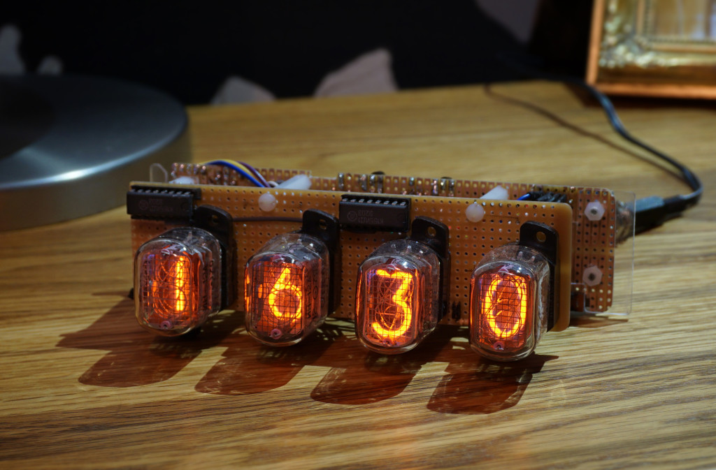
We’re well overdue a part two to the Arduino GPS clock project. Time has passed – beautiful orange, high voltage, obsolete, Russian Nixie time – the clock is coming along nicely and I’ve only given myself four electric shocks…
so far.
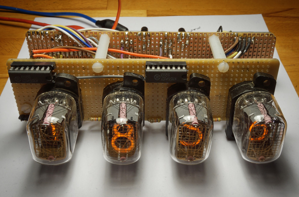
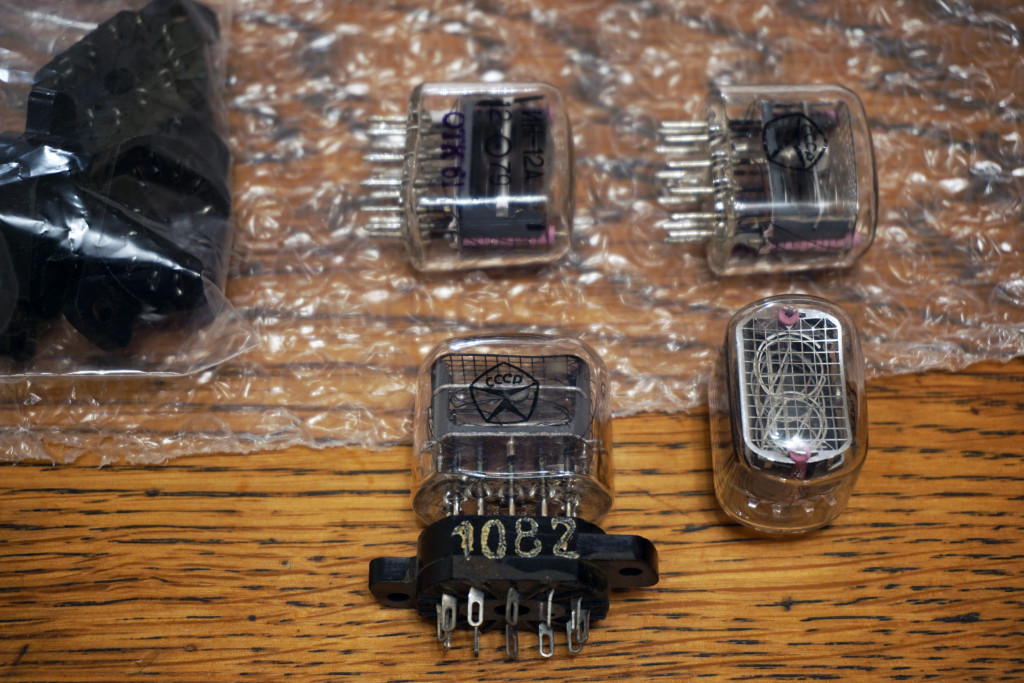 IN-12A Nixie tubes
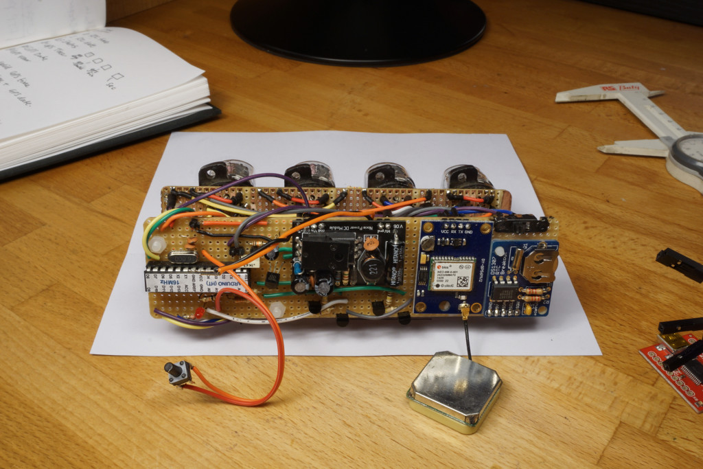
Previously, I cobbled together a serial GPS receiver module (ublox NEO-6 GPS) with an Arduino (ok, not really an Arduino, a home brew ATMega328 with an UNO boot loader) and managed to somehow extract the current time. Spurred on by this success I went on a spending spree and bought four IN-12A Nixie tubes, cheated and bought a little pre assembled high voltage power supply PCB and some K155ID1 drivers. The PSU I bought consists of an L7805 voltage regulator and a max1771, giving us 5v and 180v from a 9v input.
The K155ID1 ICs are BCD to decimal high voltage drivers. They have four binary low level 5v inputs with 10 output pins, one for each digit on the tube. These outputs can directly drive the high voltage Nixie cathode. They’re a Russian version of the 74141 which is now almost impossible to get hold of. As far as I know, the K155ID1s aren’t manufactured any more either but they are at least available to buy, for now.
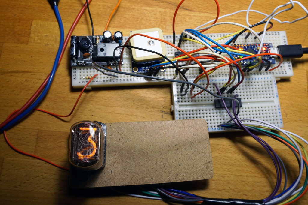 Success with an Arduino Nano and a 74HC595 shift register feeding a K155ID1 IC
Originally, I decided to use two 8 bit 74HC595 shift registers to control my four Nixie tubes. That’s two 4 bit digits per 595. Which would look something like this:
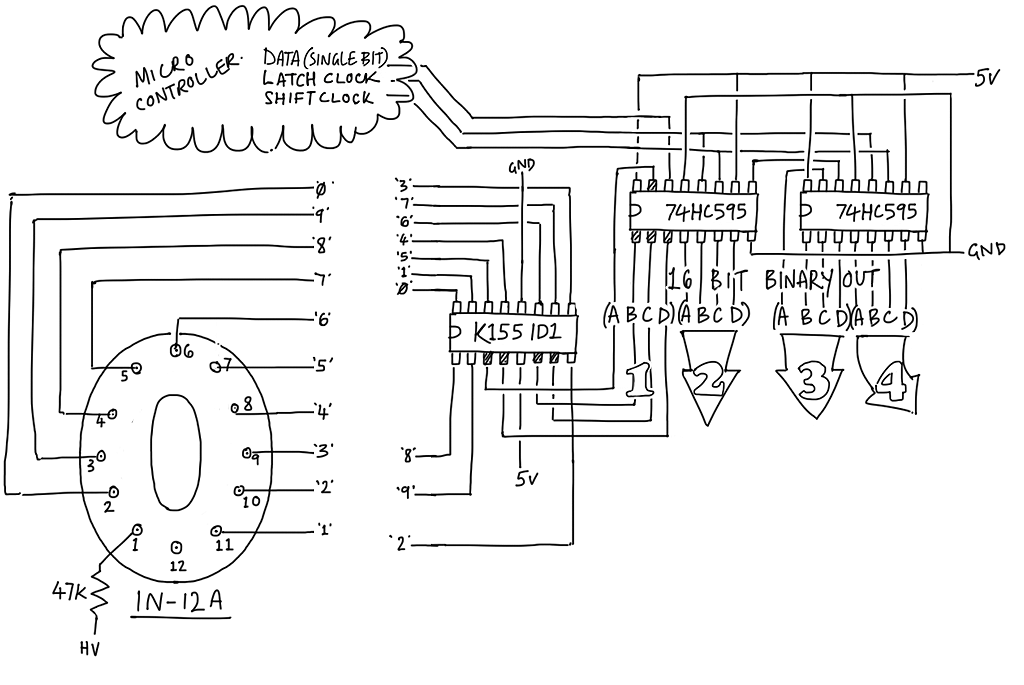 First idea, two shift registers and a driver IC per Nixie
Surely the easiest way to drive the Nixies: just three pins used on the micro controller, with a driver per Nixie. I’d only have to write data out every minute (whenever the time changes). But that’s four K155ID1s and at the time of my mad spending spree the shop only had two in stock. Too impatient to wait, I went with a different idea.
Multiplexing
Multiplexing would allow me to drive four tubes from two K155ID1 drivers (or probably even from just one) with 8 output pins on the micro controller. Each driver would be connected to two Nixie tubes. The micro controller then turns on two digits, sends the two numbers to the drivers, maybe wait a few milliseconds, turns those tubes off and the others on and sends the two digits, waits a bit… and repeat forever. Do this quickly enough and the four Nixies look like they’re all on all the time.
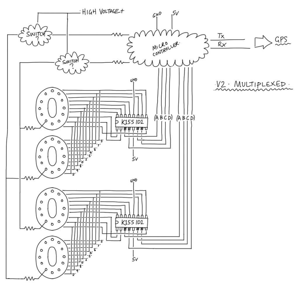 Multiplexed, two Nixie tubes per K155ID1 driver
I recall reading somewhere that multiplexing like this would also extend the life of the tube by not allowing them to burn full on constantly. Although I’m not 100% sure that is correct. I’ve also read the opposite is true, hammering these on and off could shorten their life? *shrug* I’ve noo idea. Certainly by not lighting these up to their full brightness their life should be extended and pulsing like this does do that I suppose but then driving them directly at the same brightness as multiplexed would take less current and therefore extend their life. Driving them directly wins then? Yet still for some reason I continued with multiplexing.
I’ve done simple multiplexing before, the difference here is the scary high voltage. I can’t just switch these things on and off directly from a pin on the micro controller. Thankfully, Nixie tube clocks have been done to death, the internet is awash with them, everyone and their dog has a blog about self built Nixie clocks… er… yeah. So after a bit of reading around I discovered the way to go was to use two high voltage MPSA42 and MPSA92 transistors. I forget where exactly I stole this idea from but it seems like everybody is doing it as the Nixie shop that sold me the K155ID1 ICs also sold these.
Back to the web site to buy then. Ironically there were now more K155ID1s in stock, tempted to ditch the multiplexing and just buy two more driver ICs and do it the easy way… but I’d invested so much time playing around with multiplexing that I had to see it through. And it seemed a waste to use more scarce ICs than I really needed. Meh. I bought two more K155ID1s anyway, I’m sure to blow one up and if not there’s always Nixie clock mk2.
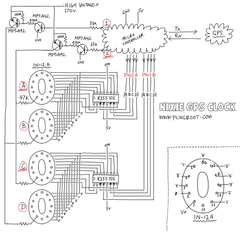 Switching pairs of Nixies from the micro controller
Now, output pin 2 on the micro controller will switch digits A and C on or off and pin 1 will control digits B and D. A quick breadboard test with the multimeter and sure enough, scary high voltage was switching away, it worked.
Simple code to display 1234 across the digits would look something like this:
// simple multiplexing
// output pins to the K155ID1 drivers
byte pinsA[] = {5, 6, 7, 8};
byte pinsB[] = {9, 10, 11, 12};

void loop()
{
 delayMicroseconds(1000);

 // pins 1 and 2 are outputs to switch pairs of nixie digits.

 digitalWrite(1,0);
 digitalWrite(2,1);  // digits A and C on

 // send binary values for hours tens and mins tens

 for (i=0; i<4; i++)
 {
   digitalWrite(pinsA[i], bitRead( 1, i));
   digitalWrite(pinsB[i], bitRead( 3, i));
 }

 delayMicroseconds(1000);

 digitalWrite(2,0);
 digitalWrite(1,1); // digits C and D on

 // send binary values for hours units and mins units
 for (i=0; i<4; i++)
 {
   digitalWrite(pinsA[i], bitRead( 2, i));
   digitalWrite(pinsB[i], bitRead( 4, i));
 }
}
Great, but... we have to loop through this constantly. Unlike the shift register method I can't just send the data whenever I like. Any slight unexpected pauses and there will be flicker / only two digits displayed / ghosting of an neighbour's number / all manner of mess. Timing is now critical, as I found out...
Failed multiplexing, it should show 1017
This horrible flickery eyesore was thanks to the software serial library. I was using the micro controller's hardware serial for the GPS module and software serial on a couple of spare pins as a debug monitor. The critical timing required for serial comms was interrupting the display updates. I explored various other leaner serial libraries, removed the ugly blocking delays with something more elaborate but in the end... flicker happens when debugging. With debugging and software serial removed the flicker is gone. It shouldn't impact the final clock.
Better, cleanly displaying 1133/2244
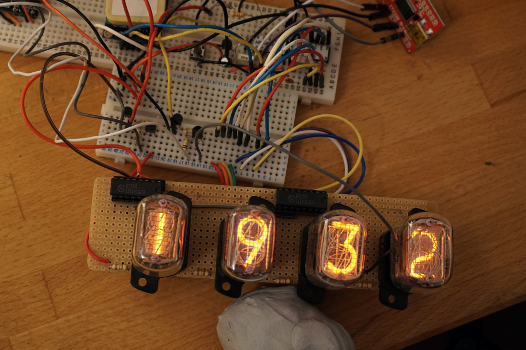 Look, the actual time
So far so good. Now I'm able to read the time from the GPS receiver and display it on multiplexed high voltage Nixie tubes... surely it's pretty much finished? But wait, the GPS module is sealed in a thick box, it's a cloudy day (it's always a cloudy day!) and very indoors (a prison-cell grade tiny windowed room, with curtains most likely drawn, indoors. A light-less dungeon with my pale sickly sun-starved self cowering in the corner, stroking my precious yet hopelessly inaccurate clock? In other words a bit of GPS blind spot). For the majority of the time there won't be a GPS signal. I can't rely on the GPS receiver as a source of time at all. The general time keeping needs to be done elsewhere, with the GPSr only occasionally setting the time as and when it can.
Real time clock
I had this Adafruit RTC thing lying around. It was meant for some Raspberry Pi project that never came to be. I enlisted it onto the Nixie clock project. Battery backed, it will also keep time when the clock is off.
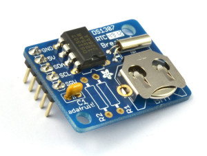 DS1307 Real Time Clock
I later discovered that the DS1307 is not particularly accurate but it will do. It shouldn't be relying on this for long periods of time anyway, the GPS, hopefully, fingers crossed (and curtains open), will be keeping the clock on time. It uses I2C, that's pins A4 and A5 on the ATMega328... time for a new diagram then :
 A more complete diagram
Simple code to set and retrieve thanks to Adafruit's RTC Library : https://github.com/adafruit/RTClib
// set and retrieve RTC time #include#include "RTClib.h" RTC_DS1307 RTC; DateTime now; void setup() { // RTC Wire.begin(); RTC.begin(); //setting RTC.adjust( DateTime(2015,1,5,20,24,00) ); } void loop() { //retrieve now = RTC.now(); Serial.print(now.day()); Serial.print("/"); Serial.print(now.month()); Serial.print("/"); Serial.print(now.year()); Serial.print(" "); Serial.print(now.hour()); Serial.print(":"); Serial.println(now.minute()); }
A lot of soldering later...
 Back
Back
 Front
Front
A nice wooden box later :
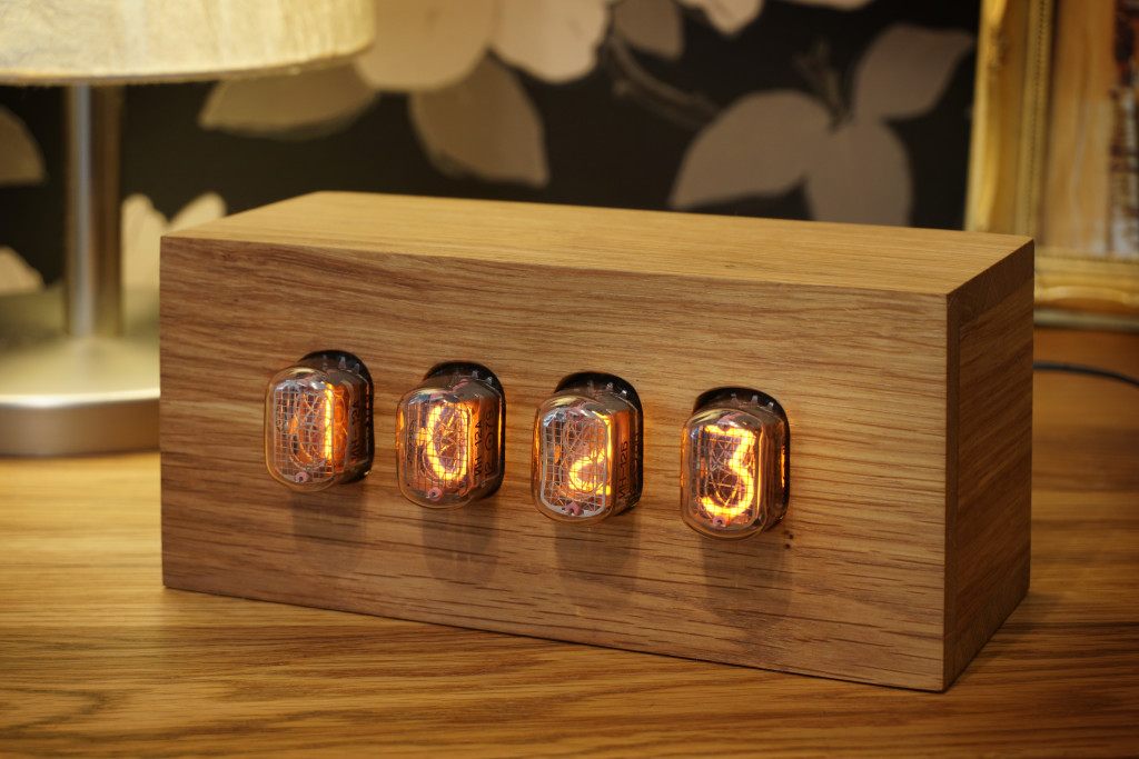 Finished Nixie clock
Whenever there is a valid GPS date and time, not necessarily a full fix, it will set the time if it hasn't been set recently, currently 12 hours. Surprisingly it works well. If left long enough it even claims to find a full GPS fix from my dark dungeon like room. I'm not sure I believe it.
A single button on the back flips between various modes :
- 1 : RTC Time : Hours / Minutes
- 2 : RTC Time : Minutes / Seconds
- 3 : RTC Date : Day / Month
- 4 : RTC Date : Year
- 5 : GPS Status
- 1st digit : 1 = valid GPS time / 2 = valid GPS time and date
- 2nd digit : GPS read status: 5 = matched GPRMC header / 1 = Serial OK
- 3rd digit : Full GPS fix : 1 = Yes / 0 = No
- 4th digit : RTC Seconds
- 6 : Date of last sync : Day / Month
- 7 : GPS Time : Hours / Minutes
- 8 : GPS Time : Minutes / Seconds
- 9 : GPS Date : Day / Month
- 10: GPS Date : Year
Tube saver
I did become a little obsessed with attempting the preserve these precious little Nixie tubes. I've no idea how long these things will last. Light bulbs burn out all the time, right? Is it the same for these things? Will one die in 3 weeks? 3 years? I decided to turn them on only when needed. There's no need to have these glowing away all day long when everyone's out. I toyed with motion detection. My grand idea was that whenever anyone was in the room the clock's display would be on. It worked, kind of. I bought an IR sensor. A range detector sensor, the wrong kind if I'm honest but I wanted something discrete and a proper motion sensor would be a huge and unsightly lump perched on top. I had nice code to buffer and then average out the IR sensor's input. It was even able to do all this and keep a flicker free display. It didn't really work though. Maybe more suitable for a bedside clock in which you could fling a half asleep arm at it to see a blurry 6am flash before your eyes but for my idea of detecting someone walking into a room? It was no Kinect. I gave up. Instead I hard coded it to simply blank the display between 1am and 6am. A switch on the back now controls this 'tube saving' mode.
Cathode poisoning
In addition to my Nixie lifetime anxiety was the real problem of cathode poisoning. Something to do with whatever gassy goings on occur inside the sealed tube, result in digits becoming damaged over long periods of inactivity. The first hour digit would be especially susceptible with it only ever showing 0,1 and 2 and even then hardly changing those. Apparently, I forget where I read this, but some Nixie spec states each digit must be displayed x many times per hour. This then is the reason for the many Nixie clock 'slot machine' effects you see when reading blogs like this - and to be honest, its an excuse to make something almost exciting happen when literally clock watching... and so...
*drum roll* On the hour, every hour, it does this :
And that's it. Lots of messy code and a few more electric shocks and I have my finished GPS Nixie clock.
Hi
Awsome.
Can you share the code for the finnished clock? I would realy like to build one of these my self!!
Hello,
I can’t find any contact info in the site so forgive me for using the comment section. I’m Algen, I work with engineering website EEWeb.com and would love to have your website featured as a site of the day on EEWeb. Is this of interest to you?
Hope to hear from you soon.
Sincerely,
Algen
Hello ,
I am doing the assembly of this watch but it is not indicated where the connection is made to ATMEGA terminal A1, Please show me where it is connected.
Thanks
Armando Leal
Ignore it. A1 goes to a button which is not shown on the diagram. The button is used to change modes etc.
Hello David,
would you publish your code?